

A whitepaper by Omni Design Technologies
Introduction
5G is the dominant next-generation telecommunication network expected to bring transformational changes and benefits beyond legacy standards. As data demand continues to grow, and the applications of various network systems expand year after year, 5G will power the capacity growth needed by industries and consumers. It will support diverse use cases based on significantly improved data rates, latency, connectivity, and reliability. Deployment gained momentum in 2020, with both field trials and commercial implementations on-going. This whitepaper provides an overview of the key technologies, challenges, and architectural solutions related to the 5G revolution.
Application and Use of 5G
5G deployment use cases can be categorized into three broad areas: enhanced mobile broadband (eMBB), ultra-reliable and low-latency communications (URLLC), and massive machine-type communications (mMTC) [1]. Each use case has a different set of technical requirements with performance parameters including peak data rate, spectral efficiency, latency, connection density, reliability, and many more.
5G deployment will initially focus on eMBB that will offer a seamless experience to consumers. These applications include 4k and 8k streaming, AR/VR, and low-latency access to the cloud. Bandwidth may vary from 100MHz to 1GHz depending on the frequency band; lower frequency bands will have lower bandwidth due to the legacy narrow channel width in earlier communication standards. URLLC demands stringent requirement of 1ms latency and 99.999% reliability. It will be essential for vehicle-to-vehicle communication, mission critical applications, tactile applications, and certain industrial automations. Lastly, mMTC will have a large impact on IoT adoption. Wearables and sensors fall into this category, with potential connection densities of one million devices per square kilometer, a significant increase from 4G capabilities.
Key Enabling Technologies
The scope of technological advances in 5G is very broad and continues to grow. This section outlines a few of the most significant changes relative to what has been available in legacy standards, including millimeter-wave (mmWave), massive multiple input multiple output (MIMO) systems, and small cell.
Millimeter-Wave
5G New Radio (NR) is the global standard for the 5G network. As shown in Figure 1, it includes two distinct frequency bands: sub-6GHz (e.g., 2.4GHz and 5GHz), and mmWave that extends from 24GHz to 100GHz. In the sub-6GHz bands, existing infrastructure can be upgraded to enable rapid 5G deployment. 5G installations are currently in progress in the sub-6GHz domain. However, sub-6GHz bands are congested with numerous applications, including 4G, and have limited bandwidth constrained by the standards of previous generations. The mmWave spectrum is largely unused and offers significantly higher bandwidths — up to 1GHz [1][2]. Several frequency bands between 24GHz and 100GHz are being considered; 24GHz and 39GHz are of especially high interest [3].

One drawback of mmWave is its limited physical range compared to that of the sub-6GHz band. At high frequencies, propagation loss is severe, and signal is much more susceptible to blockage from obstacles. It is well known that rain attenuation, atmospheric and molecular absorption is exacerbated within the millimeter wave spectrum [1].
Massive MIMO
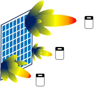
MIMO is a radio link technology that leverages multiple transmitters and receivers to improve signal performance. It has widely been used to enhance connectivity and its core techniques include spatial diversity, spatial multiplexing, and beamforming [4]. Spatial diversity provides robust and reliable communication via multipath signaling using multiple antennas. In this scheme, each antenna is spaced apart and sees a different input signal. The transmitted signal is mathematically estimated from collection of received signals. Spatial multiplexing increases data rate by utilizing multiple independent spatial streams between the transmitter and receiver antenna. A common configuration is 2×2 or 4×4 MIMO, in which data rate is improved theoretically by factor of 2 and 4, respectively. In practice, the actual throughput will depend on the signal-to-noise ratio (SNR) of the channel and correlation between the channels. Lastly, beamforming is a technique that directs signal to a specific direction and maximizes the power at the receiver while reducing interference for nearby receivers. This improves throughput and overall system capacity. Figure 2 shows an illustration of massive MIMO beamforming.
In 5G networks, massive MIMO will deploy a much higher number of antennas and transceivers relative to legacy systems, further extending the performance gains of MIMO. Theoretically, MIMO can benefit from an arbitrarily large number of antennas. Current commercial solutions include 64TX and 64RX for base station deployment compared to the 4 transceivers in 4G LTE [5]. A massive MIMO radio will contain a top panel for antenna elements, and additional layers for analog/RF and digital circuitry. These components are highly integrated in a few packed boards to minimize footprint and interconnection.
Small Cell
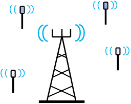
Small cells are used to cover smaller geographical areas than macrocells, and consist of femtocells, picocells, and microcells. These cell types have varying coverage radius, output power, and intended number of users. Small cells are needed in ultra-dense networks to increase data capacity, and to cover small spaces both indoors and outdoors. They can service inter-site distance of 200m and improve both coverage and capacity [6]. It is critical in mmWave because signals at these frequencies cannot penetrate buildings and have limited range. Sub-6GHz base stations will leverage existing networking infrastructures, and will provide larger areas of coverage, as shown in Figure 3. In contrast, mmWave will rely on new small cell infrastructures to serve smaller hotspots where data demand is unusually high [7].
Hardware Architectures
The complexity of 5G hardware implementation is nontrivial. Large antenna arrays lead to many signal channels and increased need for processing power. Different beamforming methods and transceiver architectures must be explored to determine feasible solutions based on individual applications [7].
Beamforming Solutions
Massive MIMO uses large antenna arrays and requires many RF chains consisting of data converters, filters, mixers, switches, PGAs, LNAs, etc. The need for large numbers of RF chains leads to increased power consumption and cost. Therefore, beamforming approaches should be carefully considered as it will determine the number of components and configurations in the RF chain[1][8].
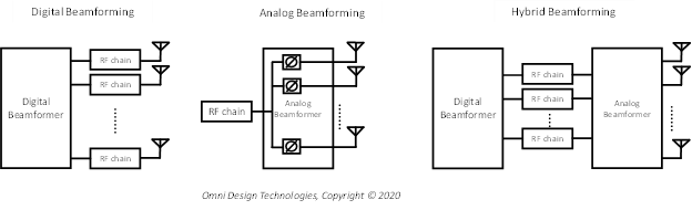
Beamforming can be done in digital, analog, or hybrid mode as shown in Figure 4. Digital beamforming has the most flexible signal processing capabilities since the amplitude and phase control is done in digital baseband. However, it requires an RF chain for each antenna and results in a large number of components, high power consumption, and increased complexity. In systems with very large number of antennas, as would be plausible in mmWave deployment, the correspondingly large number of RF transceivers needed for implementing digital beamforming would significantly increase implementation cost.
Analog beamforming is the traditional approach and requires only one RF chain. Signals are adjusted in the analog domain via phase shifters and gain control before the antenna. Although simple and cost effective, analog beamforming offers less reconfigurability and spatial resolution.
Hybrid beamforming is of high interest as it combines both digital and analog beamforming. It offers greater flexibility than analog beamforming, reduced complexity, and lower cost than pure digital beamforming owing to the lower number of RF chains required. Signal processing is carried out in both the digital and analog domains. Hybrid beamforming reduces complexity and hardware cost relative to digital beamforming, while still being able to facilitate multi-stream processing in contrast to analog beamforming.
Transceiver Silicon Implementations
The implementation of the transceiver system in discrete solutions leads to a large footprint and high power consumption. It would be difficult to integrate many channels on a PCB. The components are bulky and it would be challenging to have many high speed interfaces to move data between the digital processing module and the data converters. This approach does not scale efficiently in 5G as the number of channels are drastically higher than in previous generations, and a more flexible platform is needed to handle the evolving requirements of 5G. The solution ultimately requires the integration of analog modules into the SoC. This significantly reduces footprint and enables massive MIMO to be natively supported. Also, it eliminates complexity of routing high-speed signals between discrete components.
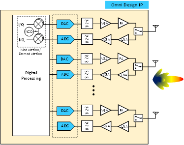
Figure 5 shows a direct-RF transceiver suitable for sub-6GHz 5G [9]. Unlike a superheterodyne transceiver, the signal up/down conversions are handled digitally in the direct-RF architecture via a numerically controlled oscillator (NCO). This architecture improves platform flexibility and performance while eliminating analog and RF impairment. The programmability makes the platform suitable for various sub-6GHz frequencies since all frequency translations are handled digitally.
In the transmitter, the signal is digitally upconverted to RF. A higher up-sample ratio eases the filtering requirements that follows the DAC. The DAC output is an RF signal that goes through image filtering and amplification via VGA and PGA. In the receiver, the LNA, VGA, and filtering provides the necessary analog signal processing before the data conversion. An RF signal is sampled by the ADC and finally down converted in the digital domain.
The intermediate-frequency (IF) architecture shown in Figure 6 is a potential solution for mmWave application. Since mmWave applications run on much higher frequency bands than in sub-6GHz, it is necessary to have signal processing at the transceiver front-end in analog/RF domain and handle signal processing between baseband and IF in the digital domain. The transmitter upsamples and performs upconversion to IF frequency in the digital domain similarly to in the direct RF transmitter. After filtering, the signal carrier is translated to the mm-wave frequency in the phased-array IC. In the receiver, the signal is down-converted to IF frequency in the phased-array IC and goes through additional down conversion digitally. Although the architecture in Figure 6 is for digital beamforming where the phase is adjusted via digital signal processing, the IF architecture can be extended for other beamforming approaches as well. For example, the phase shift can be accomplished in the mmWave frequency [10].
Omni Design’s Solution for 5G
The speed requirements for 5G data converters range from hundreds of MSPS to multi-GSPS, and from 10 to 14-bits in resolution. Advanced nodes enable better power efficiency and a more compact area. Omni Design offers a wide array of data converter IP solutions for 5G applications. A partial list of data converter IP products is listed in Table 1. Solutions are offered in multiple process nodes from 28nm to advanced FinFET nodes, and Omni Design’s patented and proprietary technologies enable data converters to operate at higher sampling rates and precision while significantly reducing power consumption. These proprietary techniques also enable design of high-speed converters at low supply voltages that are typically associated with advanced finFET process nodes. Also, the ADCs and DACs include clock synchronization circuits to support phased array implementations.
| Product Name | Resolution (bits) | Speed (MSPS) |
| ODT-ADP-14B1P2G-28 | 14 | 1200 |
| ODT-ADP-14B600M-28 | 14 | 600 |
| ODT-ADP-14B300M-28 | 14 | 300 |
| ODT-ADS-12B6G-16 | 12 | 6000 |
| ODT-ADS-12B2G-16 | 12 | 2000 |
| ODT-DAC-12B7G-16 | 12 | 7000 |
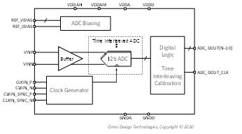
The ADC IP products are designed to include any required foreground and background calibration for correcting various non-idealities such as time-interleaving artifacts and capacitor mismatch. Omni Design’s proprietary interleaving and calibration technology enables converters to be compatible with wireless communication requirements. This technology removes any unwanted spectral notches that can be observed in many other time interleaving correction algorithms. For example, ODT-ADS-12B6G-16, part of our Lepton™ (12-bit) ADC family, in Figure 7 is a high-performance time-interleaved ADC. This 12-bit 6GSPS ADC supports input signals up to the Nyquist frequency, and features SNR and SFDR of 56dB and 62dB, respectively. The designs of the data converters leverage Omni Design’s proprietary platform-based development methodology that enables the design of these converters using modular building blocks that results in a substantial reduction in schedule and product risk.
Omni Design’s RF-DAC IPs can be leveraged to generate wide-bandwidth modulated waveforms. For example, ODT-DAC-12B7G-16, part of our Lepton™ (12-bit) DAC family, in Figure 8 is a high-performance current-steering 12-bit DAC that operates at an update rate of up to 7GSPS. The DAC uses a proprietary architecture that reduces harmonic and intermodulation distortions at high output frequencies and amplitudes. It also includes a direct digital synthesizer for signal generation.
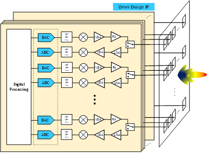
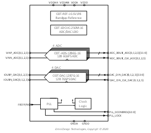
Integrating multiple high-speed data converters at the AFE level requires extensive design and verification efforts. Omni Design provides all the necessary deliverables and support to enable the integration of the AFE into the customer ASIC, including analog, digital, scan chain, behavioral models, and detailed integration documentation. Third-party phase-locked-loop (PLL) IP products are included in the AFE, and any clock division, synchronization, or routing is handled internally. The ODT-AFE-4T4R-16 in Figure 9 is an example of a high performance AFE. It supports four ADCs and four DACs. The AFE also includes bandgap references and low-dropout voltage regulators (LDOs) to generate clean supply voltages and references to multiple analog/mixed-signal IPs.
Summary
The acceleration of 5G deployment will demand significant innovation across multiple domains to fulfill its potential. Among the key challenges is the implementation of flexible and cost-efficient hardware. Different architectures will need to be considered based on performance, capacity, cost, and footprint requirements. High-performance silicon IP will play an essential role in facilitating the overall system development. A portfolio of IP products with state-of-the-art power efficiency, form factors, and integration support are needed to meet the stringent and evolving specifications. Omni Design is already delivering the leading mixed-signal solutions necessary to enable the coming 5G era.
References
- M. Shafi et al., “5G: A Tutorial Overview of Standards, Trials, Challenges, Deployment, and Practice,” in IEEE Journal on Selected Areas in Communications, vol. 35, no. 6, pp. 1201-1221, June 2017
- Yong Niu, Yong Li, Depeng Jin, Li Su, and Athanasios V. Vasilakos. 2015. A survey of millimeter wave communications (mmWave) for 5G: opportunities and challenges. Wirel. Netw. 21, 8 (November 2015), 2657–2676.
- M. Ali et al., “First Demonstration of Compact, Ultra-Thin Low-Pass and Bandpass Filters for 5G Small-Cell Applications,” in IEEE Microwave and Wireless Components Letters, vol. 28, no. 12, pp. 1110-1112, Dec. 2018
- S. Sun, T. S. Rappaport, R. W. Heath, A. Nix and S. Rangan, “MIMO for millimeter-wave wireless communications: beamforming, spatial multiplexing, or both?,” in IEEE Communications Magazine, vol. 52, no. 12, pp. 110-121, December 2014
- W. Honcharenko, “Sub-6 GHz mMIMO base stations meet 5G’s size and weight challenges”, Microw. J., no. 62, pp. 40-52, Feb. 2019………………Column Break………………
- S. A. Busari, S. Mumtaz, S. Al-Rubaye and J. Rodriguez, “5G Millimeter-Wave Mobile Broadband: Performance and Challenges,” in IEEE Communications Magazine, vol. 56, no. 6, pp. 137-143, June 2018
- J. G. Andrews et al., “What Will 5G Be?,” IEEE JSAC, vol. 32, no. 6, June 2014, pp. 1065-82
- Ahmed et al., “A Survey on Hybrid Beamforming Techniques in 5G: Architecture and System Model Perspectives,” in IEEE Communications Surveys & Tutorials, vol. 20, no. 4, pp. 3060-3097, Fourth quarter 2018
- B. Jann et al., “21.5 A 5G Sub-6GHz Zero-IF and mm-Wave IF Transceiver with MIMO and Carrier Aggregation,” 2019 IEEE International Solid- State Circuits Conference – (ISSCC), San Francisco, CA, USA, 2019, pp. 352-354
- H. Kim et al., “A 28GHz CMOS direct conversion transceiver with packaged antenna arrays for 5G cellular system,” 2017 IEEE Radio Frequency Integrated Circuits Symposium (RFIC), Honolulu, HI, 2017, pp. 69-72