

Understanding ADC Performance Specifications
By Omni Design Technologies
Abstract
Analog-to-digital converters (ADCs) are widely used in audio/video devices, cell phones, medical imaging, and RADAR/LiDAR applications. ADC converts an analog signal into a digital signal. In the real world, the conversion from an analog signal to its digital equivalent introduces errors that affect the ADC performance specifications. ADC performance is measured by static and dynamic parameters. This document details commonly used ADC performance specifications of ADCs.
ADC Performance Specifications
Resolution
The resolution is the number of bits in the converter and is a well-known specification that goes along with speed. Resolution determines the size of the least significant bit (LSB) and the quantization noise.
Sampling-Rate
Sampling-Rate is the speed at which ADC samples the input. In successive approximation (SAR), pipeline, and flash ADCs, the sampling rate is equivalent to the output data rate. In sigma-delta ADCs, the output data rate is significantly higher due to oversampling.
Differential-Nonlinearity (DNL)
Differential-Nonlinearity (DNL) is the deviation from the 1 LSB code transition width. An ideal converter has a code width of 1 LSB throughout all codes, and therefore the DNL would be zero. A DNL of greater than -1 LSB will guarantee monotonicity and no missing code.
Integral-Nonlinearity (INL)
Integral-Nonlinearity (INL) is the deviation of the code centers from the ideal transfer function of a straight line. There are two options to choose from for the ideal transfer function. One option is the line that connects two endpoints, the maximum and minimum endpoints. A second option is the best fit line that minimizes the overall measured INL.
Offset-Error
Offset-Error is the difference in the first transition voltage from the ideal transition voltage. In a bipolar ADC, offset is the differential input voltage that will produce mid code for ADC output. Offset error affects all codes by the same amount and it can be easily calibrated.
Gain Error
Gain Error is the deviation of the difference between the actual level of the last transition and the actual level of the first transition from the difference between the ideal transition levels.
Signal-to-Noise Ratio (SNR)
Signal-to-Noise Ratio (SNR) is the ratio of the rms value of the input signal to the rms sum of all other spectral components below the Nyquist frequency, excluding harmonics and dc, and is expressed in the decibel (dB) scale. The minimum analog-to-digital noise is caused by quantization noise error only and results directly from the ADC’s resolution (N bits):
SNR = (6.02 x N + 1.76) dB
The thermal noise and quantization noise are the biggest contributors to the noise power. Harmonic distortions up to the 6th order distortion are excluded in the calculation. Also, in a time-interleaved ADC, the time-interleaving spurs that arise from offset, gain, and skew mismatch between channels are excluded as well. In high-speed ADCs, the PLL jitter can significantly increase the overall noise power and degrade the SNR. It is recommended that the jitter noise is removed by excluding a range of sideband noise near the fundamental signal tone to get a more accurate measurement of the ADC noise level.
Spurious Free Dynamic Range (SFDR)
Spurious Free Dynamic Range (SFDR) is the ratio of the RMS voltage of the fundamental signal tone to the largest spurious spectral component within the Nyquist band and it is specified relative to full-scale input (dBFS) or the actual input level (dBc). The spurs are generated at harmonics of the input frequency, and at frequencies related to the clock, subsampling clocks, and interleaving frequencies. SFDR can be specified with or without HD2 and HD3 terms. SFDR is a very important metric in communication systems since the spurs frequently occur within the bandwidth of interest and cannot be distinguished from a real signal.
Distortion
Second-Harmonic Distortion (HD2) spur falls at twice the frequency of the fundamental.
Third-Harmonic Distortion (HD3) spur falls at thrice the frequency of the fundamental.
Total Harmonic Distortion (THD) is the ratio of the sum of powers of harmonics to the fundamental signal power. Typically, the first six harmonics are considered for the THD.
Signal-to-Noise Distortions (SNDR) measure the signal power relative to all spectral components that come from noise and distortion power. The RMS noise voltage includes the thermal noise and the quantization noise as discussed in the SNR metric. The RMS distortion noise voltage includes distortion from all harmonics, time-interleaving spurs, and any other distortion spectral components.
Dynamic range
Dynamic range is the range of signal amplitude that the data converter can resolve. It is defined as the ratio of maximum full-scale output level to the noise floor and is expressed in dBs. Although the dynamic range is often like the SNR, however, the noise floor varies with respect to signal strength. Dynamic range is important in communication applications, where receiving signals may have varying signal strengths. Typically, a VGA/PGA is placed ahead of the ADC to normalize the signal amplitude before processing the data conversion.
Aperture Delay
The Aperture Delay is the delay between the sampling trigger that typically comes from either the rising or falling edge of the sampling clock and the actual sampling moment.
Aperture Jitter
The Aperture Jitter is the variation of aperture delay from sample to sample. Aperture jitter behaves like a random noise source and degrades SNR. The SNR degradation becomes more severe at high input frequencies.
Effective Resolution Bandwidth (ERBW)
ERBW is the input frequency at which the SNR degrades by 3dB for a full-scale input signal.
Effective Number of Bits (ENOB)
ENOB is a commonly used metric to measure the dynamic performance of the ADC. Higher ENOB is associated with better data conversion accuracy.
Amplitude Imbalance
Amplitude Imbalance indicates the degree of amplitude mismatch across channels in multi-channel ADCs. It is the maximum deviation in amplitude and is reported in decibels.
Phase Imbalance
Phase Imbalance indicates the degree of phase mismatch across channels in multi-channel ADCs. It is the maximum deviation in phase and is reported in degrees.
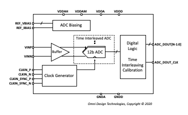
A typical high speed ADC block diagram
| www.omnidesigntech.com support@omnidesigntech.com sales@omnidesigntech.com Phone: 408-727-6377 1525 McCarthy Blvd, Ste 220 Milpitas, CA 95035 |